Powered Wheelchair Seat Stabilization System
Mikhail A. Golovin1,2
1Federal State Budgetary Institution «Federal Scientific Center of Rehabilitation of the Disabled named after G.A. Albrecht» of the Ministry of Labour and Social Protection of the Russian Federation (Saint-Petersburg, Russia),
2Peter the Great St.Petersburg Polytechnic University (SPbPU)
(St. Petersburg, Russia)
Keywords—rehabilitation, people with disabilities, robot, control system, wheelchair
Topicality
At the moment, there is no scientifically based methodology for designing wheelchairs taking into account the specifics of urban infrastructure. Existing ways to ensure accessibility of megalopolis infrastructure facilities for people with disabilities can be divided into two groups: adaptation of infrastructure or increasing the mobility of people with disabilities. Increased mobility is associated with the development of fundamentally new vehicles that maximize the capabilities of people with disabilities.
The aim of the study is to develop a layout of a stabilization platform for a mechatronic wheelchair. The objectives of the study are to design the elements of the stabilization module and their subsequent manufacture by an additive manufacturing process.
The relevance of the research to develop a mechatronic system is to create a unique chassis system. Currently, there are no constructions of robots, robotic complexes, and in particular wheelchairs, including mass-produced ones and models that allow moving an object along an escalator, despite the high frequency of their occurrence in objects of social and domestic urban infrastructure. This movement is possible only with the involvement of unauthorized persons and the use of various assistive devices. Such devices include, for example, staircases. The development of the chassis for entry, movement and exit from the escalator will significantly expand the capabilities of the wheelchair operator. At the same time, the use of the modular design principle, that is, the use of the same modules to ensure the necessary (for example translational) movement, as well as increasing their energy efficiency, will improve the manufacturability and operational characteristics of a wheelchair.
Methods and materials

It is proposed to use a stabilization system based on four modules. Each of the modules provides vertical movement. During the study, two options were proposed for the stabilization module with a balancing system based on a non-linear spring battery with a sine characteristic (Figure 1).

For the chosen arrangement with cylindrical tension springs, electronic geometric models of parts were built, including pulleys and a belt, taking into account the use of unified metric fasteners, as well as strength analysis by the finite element method for the case of manufacturing parts using an additive technological process of material extrusion. The optimum dimensions of the parts were obtained. As a result, the stabilization module was developed in CAD SolidWorks (Fig. 2, a). The constructed model was then imported into Matlab software to build a mathematical model of the model nodes movement (Fig. 2b).

Further, on a 3D printer, belt parts, including a belt, were also grown. After this, a layout was built with four developed stabilization modules.
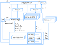
Figure 4 shows the structural and functional diagram of the platform. A 12V lead gel battery and two DC-DC converters are used as an energy source: 5V and 6V. Servo drives SG-6221 are used as translational vertical displacement drives. They are powered by 6V, each drive consumes 1A. To move the platform, DC motors are used, which are connected in pairs to the L298D driver. In this regard, the right and left sides can be controlled separately. In this case, the driver regulates not only the direction of rotation of the motor wheels, but also change the speed of their rotation. Also, with the opposite movement of the drives of the left and right sides, a turn in place becomes possible.
A five-position joystick and potentiometer are used as a control controller. The joystick indicates the direction and speed of movement, as well as the direction and speed of rotation. The potentiometer allows the operator to manually adjust the height of the stabilization platform.
The following sensors are installed on the platform: IMU and height sensors. The IMU records the change in position (deviation) of the platform from the horizon in three planes. Height sensors record the height to the surface of the movement, after which the microcontroller is able to determine the presence of a surface slope until the moment of entry.

The board used with the ATMega family microcontroller has the necessary components for connecting all drivers, drives, sensors, power supplies. The values from IMU are filtered on it, due to which the deviation angles in three planes are constantly recorded with minimal error. With drives of motor wheels, it is possible to realize the recovery of electrical energy.
Discussion
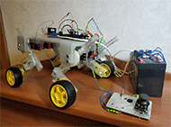
The resulting layout has the following properties. Implemented an independent suspension of each wheel. The operator gets the opportunity to move forward, backward, turning and turning on the spot. The possibility of a synergistic effect from the stabilization modules is used - to uniformly move the platform up and down.
The rate of change of height, that is, the speed of vertical movement of the fulcrum, depends on the maximum angular velocity of the servo used.
Conclusion
As a result of the work, a kinematic scheme was proposed and a stabilization module with a balancing system based on a cylindrical tension spring was designed. The details of the mock module are designed with and manufactured by the additive manufacturing process for the extrusion of the material. A version of the stabilization platform with four modules has been developed. The structural and functional diagram of the designed system is proposed. It is of scientific interest to study the designed platform and the proposed designs of stabilization modules.
REFERENCES
- Korendjasev A.I., Salamandra B.L., Tyves L.I. Manipuljacionnye sistemy robotov [Manipulation systems of robots]. Moscow, Mashinostroenie, 1989, 472 p.
- Zhavner V.L., Abramov A.M., Macko O.N., Zhavner M.V. Mehatronnye rekuperativnye privody dlja ciklovyh peremeshhenij: ucheb. posobie [Mechatronic recuperative drives for cyclic movements: a training manual]. Velikiy Novgorod, Federal State Budgetary Educational Institution of Higher Education "Yaroslav-the-Wise Novgorod State University"(NovSU), 2013, 87 p.
- Anur'ev V.I. Spravochnik konstruktora mashinostroitelja. tom3 [Engineering Designer Handbook. vol.3]. Moscow, Mashinostroenie, 2001, 864 p.
Acknoledgment.
The reported study was funded by RFBR, project number № 19-38-90262.