Benjamin Tham, Andrew Spencer, Ali Hawkins, Thai Quach, Ben Coe
LeTourneau UniversityProblem Statement and Background
Transfemoral amputees' ability to ambulate is dependent upon and restricted by the prosthetic device that is used to simulate the functions of lost muscles and bones. Depending on the amputees' potential to use a prosthetic device, they are often classified into four different levels (K-levels). Transfemoral amputees rated at lower K levels tend to experience falling and injury during walking especially on uneven surfaces because their prosthetic knee does not provide necessary support during the stance phase if the knee is in a flexed position, causing knee buckling. On the other hand, the cost for more stable and functional prosthetics, often used for amputees with higher K levels, may be a deterrent for amputees with low income. The goal of our project was to design, prototype, and test a cost effective yet functional knee joint that would provide the support necessary to prevent the user from falling caused by knee buckling during walking on various terrains, in addition to facilitating natural walking mechanics during the swing phase. Specifically, we primarily focused on two functions: 1) to prevent knee buckling even when the knee is in a flexed position during the stance phase of walking without completely locking the knee and thus allowing knee extension from the flexed position; 2) to provide adequate damping for generating smooth motion during the swing phase of walking.
Research/Solutions Considered
When developing the prosthetic knee, the team considered the characteristics of the human knee joint and possible mechanical solutions to imitate these characteristics. These characteristics include the muscle stability and control that provides stability at various degrees of knee flexion. Solutions proposed to imitate these characteristics were categorized into four mechanical systems; a joint for knee rotation, a flexion prevention mechanism, a control to activate the flexion prevention mechanism and a swing phase extension damping mechanism. Research on solutions for these four mechanical systems were conducted and solutions were selected based on what was deemed best appropriate to accomplish the parameters of the design.
Knee Joint Rotation
Prosthetic knees on the market today mainly consist of either one of two methods of rotation; a single hinge and a four-bar linkage mechanism. The single hinge mechanism pivots the knee on a single axis of rotation. The simplicity of the design allows for an economical, durable, and lightweight solution. The four-bar mechanism pivots the knee using multiple axes of rotation, which can closely mimic the biomechanics of the human knee. Additionally, the nature of the design allows for increased stability during the early stance phase.
Flexion Prevention Mechanism
The solutions proposed for this mechanism were a rope cleat, and a pawl and ratchet system. The rope cleat mechanism prevents flexion by clamping a rope, which is fixed to the upper portion of the knee joint and attached to the lower portion of the knee joint via a spring, between the upper portion and lower portion of the knee. This design was inspired by a stance control knee-ankle-foot orthosis [1]. The pawl ratchet mechanism prevents flexion of the knee by engaging a pawl to a disk with ratchet teeth that pivots around a hinge. Both mechanisms can protect the knee from experiencing further flexion (i.e., buckling) but allowing extension during the stance phase of walking.
Flexion Prevention Control
Many prosthetic knees that can prevent flexion are controlled either by a microprocessor, or by some sort of weight bearing switch. Due to the goal of minimizing costs, the use of microprocessor computers to control our knee was not considered and thus the team conducted research on various weight bearing systems compatible with the proposed flexion prevention mechanisms. For the proposed flexion prevention controls, a switching mechanism using a simple electrical circuit, activated by a small vertical displacement of the prosthetic pylon during stance were considered to be the most effective solution.
Swing Phase Extension Damping
The two main solutions considered for implementing into the knee design were the use of eddy current damping and friction damping. The eddy current damping would utilize the eddy currents created by the material properties of copper and neodymium magnets to create resistance in the rotation of the knee, thus creating damping. The proposed friction damping would create resistance in knee rotation of the knee by applying friction using a surface backed, by a compression spring, onto another surface that is fixed around a point of rotation.
Description of Final Approach and Design
After careful consideration of each systems proposed solutions and some testing, the team decided to that the knee joint consist of a four-bar linkage joint, with a pawl ratchet mechanism to prevent buckling during stance, a contact switch to control the buckling prevention mechanism, and friction damping to create swing phase extension damping. The four-bar linkage design was selected due to its articulation closely resembling that of a human knee and stability that it provides in early stance phase. The pawl ratchet mechanism was selected due to its ability to stabilize the knee at incremental angles and allow extension from a flexed knee position during stance to enable continuous motion. The contact switch control was selected because of it's simple design and consistency of unlocking the knee for the swing phase. The damping mechanism was selected due to its common use and proven ability.
Four-bar linkage

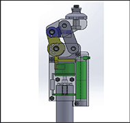
The PERK design utilized a standard four-bar linkage as the knee joint (Figure 1). The design was selected due to its articulation closely resembling that of a human knee, the stability that it provides in early stance phase and the increased toe clearance during the swing phase. The biomechanics of an able body knee exhibits not only just angular displacement but also linear displacement, which the four-bar linkage design is able to imitate compared to its single joint alternative. The four-bar linkage is also designed to increase the stability during stance when the knee angle is between 0 and ~7 degrees flexion. Additionally, the overall vertical length of the knee joint during the swing phase has been measured to decrease by approximately 4 mm from 0-60 degrees of knee flexion, thus increasing the toe clearance and minimizing tripping. However, this design would not prevent all bucking, especially on uneven terrain where the knee flexion beyond 7 degrees might occur more often at heel strike. As such, a mechanism to prevent buckling at larger knee flexion was designed (see next).
Pawl Ratchet Locking Mechanism

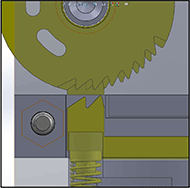
The pawl ratchet mechanism of the PERK design is utilized as a safety net for buckling prevention at a larger knee flexion angle yet allowing extension during stance. This mechanism is disengaged during the swing phase to allow free movement (Figure 2). The ratchet is included as part of both posterior center links. The pawl is designed to be pressed up against the ratchet by a spring during stance and pulled down by an electromagnet during swing. During the stance phase the electromagnet is disengaged and only the spring is pushing against the pawl, engaging the pawl-ratchet mechanism. Since the mechanism limits movement (rotation) to one direction, it can prevent knee bucking but allow knee extension during stance. Therefore, if the knee does not reach full extension just before heel strike, which might occur more often when walking on a rough or uneven terrain, this mechanism would stop the knee from buckling and prevent a fall. It also allows knee extension from a flexed position for recovery, resulting in a return to a normal stance phase.
Contact Switch Control Mechanism

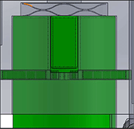
The release from the pawl-ratchet mechanism during the swing phase was achieved by an electrical circuit consisting of four 18360 batteries, a 12V DC electromagnet rated at 200N pull force and a switching mechanism. The switching mechanism consists of two contact rings, a spring and a pylon with a rectangular bar, which experiences approximately 0.5 mm of vertical displacement (Figure 3). The switching mechanism in the electrical circuit would turn off the electromagnet during stance when the pylon displaces the rectangular bar away from the contact switch. During swing when the switching mechanism does not experience any force from the ground (i.e., ground reaction force), a spring displaces the rectangular bar towards the contact rings, connecting the circuit and turning on the electromagnet. The AR-400 steel that the pawls are made of are a ferrous metal, which allows them to be pulled down and away from the ratchet when the electromagnet is on. This electronic system, working in turn with the locking mechanism of the knee, allows for a cycle of engaging and disengaging the pawl-ratchet mechanism in the knee at proper intervals to simulate the normal walking pattern.
Friction Damping Mechanism

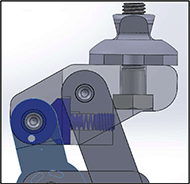
For the user to experience natural walking motion without the lower leg snapping forward during the swing phase, the prosthetic knee must decelerate the angular rotation. This was accomplished in the PERK design by implementing the proposed surface friction solution (Figure 4). The rectangular friction block is in a slot in the top of the four-bar linkage. A spring presses the rectangular friction block on to another circular friction block between the inner posterior links of the four-bar linkage. This friction between the rectangular friction block and the circular friction block slows the leg at the end of the swing phase. To meet the needs of different users, the amount of the friction was made adjustable by a set screw easily accessed from the front enables this change in spring compressive force.
Outcome
Controlled Static Testing
A static load bearing test was performed on the PERK knee using a transfemoral amputee (TFA) simulator, which enables an able-body person to simulate walking on a prosthetic knee and foot assembly. A male subject (approximately 180 lbs) wearing the TFA with the PERK knee applied his weight at various angles of knee flexion until buckling was experienced. From these tests, it was determined that the knee can consistently prevent buckling from 0 to approximately 22 degrees. However, some stretching in the nylon 12 material used in the prototype knee prevented the buckling prevention mechanism from performing to its full extent at larger angles of flexion. (The mechanism was designed to prevent bucking up to 60 degrees.)
Controlled Dynamic Testing
The same subject wearing a TFA simulator and the PERK knee walked up to 15 feet on a flat ground and filmed. It was noticed that the knee was inconsistent in locking at angles greater than approximately 10-15 degrees. Reviewing the filmed footage, it was determined that the switching mechanism was not consistently activated because the vertical component of ground reaction force applied to the prosthetic foot was not sufficient enough to activate the pawl-ratchet mechanism. However, we believe that adjusting the sensitivity of the switching mechanism would make the bucking prevention mechanism work more consistently.
Cost
Prototype cost
The budget set aside for this prototype was $700. To produce the final prototype, it cost $360. This included the 3-D printing of the clam shell, the 3-D printing of parts of the four-bar linkage, the CNC machining of the pawl and ratchet as well as purchasing of the other materials needed. The team succeeded in producing a final design under budget.
Production cost
To produce the PERK knee the number of units to be produced is assumed to be 500. Getting quotes from manufacturers about purchasing materials and parts, it was found that each knee would cost less than $100 to produce. This only includes injection molding and purchasing products needed to make the knee. Including the labor cost of the assembly of the knee would increase the expected pricing to be around $300.
Significance
Cost effective
The product was designed to be as cost effective as possible, keeping the overall manufacturing budget under $700 to target areas in low-middle income countries and keep insurance deductibles low. Most high-end prosthetics are expensive and cannot be afforded by many patients. Therefore, this solution could provide an affordable option upon further improvement.
Serviceable
The PERK knee has been designed to be easily assembled and deconstructed for repairs. The main structure of the knee is secured together with standard metric fasteners, which allows access to all the major electrical and mechanical components when removed. This allows users to service systems in home or clinic with minimal training and basic tools.
Rough terrain potential
The current prototype requires improvement to be functional for ambulating on a rough terrain where knee buckling during stance tends to occur more often. However, the tests performed in this project and the cost to produce the knee also suggest that the knee with refinement has the potential to be optimized into a viable option for transfemoral amputees who walk on a rough and/or uneven terrain with an affordable prosthetic knee joint.
References
- "Belt Clamp Design" Terris Yakimovich, Edward D. Lemaire, Jonathan Kofman. "Engineering design review of stance-control knee-ankle-foot orthoses." Rehabilitation Research and Development 46 Number 2 (2009): 257-268. <https://www.rehab.research.va.gov/jour/09/46/2/yakimovich.html
Acknowledgements
The product design, fabrication, and testing were conducted in the 2019-20 Senior Design class in the School of Engineering and Engineering Technology at LeTourneau University.