Ethan Swierski![]() 1
1![]() , Molly Burke
, Molly Burke![]() 1
1![]() , Maria Arenas
, Maria Arenas![]() 1
1![]() , Jessica Bernat
, Jessica Bernat![]() 1
1![]() , John Yankton
, John Yankton![]() 2
2![]() , James Manzer
, James Manzer![]() 1
1![]() , Elisabeth Miller
, Elisabeth Miller![]() 3
3![]() and Davide Piovesan
and Davide Piovesan![]() 1
1![]()
![]() 1
1![]() Biomedical, Industrial, and System Engineering Department, Gannon University;
Biomedical, Industrial, and System Engineering Department, Gannon University; ![]() 2
2![]() Philosophy Department Gannon University;
Philosophy Department Gannon University; ![]() 3
3![]() Sport and Exercise Department, Gannon University;
Sport and Exercise Department, Gannon University;
ABSTRACT
Cerebral Palsy (CP) is a neurodevelopmental disorder with a wide spectrum of severity. [1] Affected individuals experience irregular motor function, often to the detriment of proper gait. [1] Drop foot is a condition associated with CP in which the dorsiflexion in the leg falters, and the forefront of the foot drags during walking.[2] A common solution for this condition is the use of Ankle Foot Orthoses (AFOs)- external devices that improve gait. [3] Although these orthoses have been improved over time to address a user's physical needs, material and financial restrictions are still an obstacle. This study sought to create an orthosis that achieved these improvements by comparing different designs, materials, and configurations for their stiffness and ability to function, given the loads predicted for their use.
This study required the design of an AFO, sensitivity comparisons of material types using Finite Element Analysis (FEA) simulations, and the creation of a physical model by laser cutting thermoplastic resin in a 2D shape followed by hot drawing. The method used was ideal because it lowered manufacturing difficulty, time, and cost. Iterations of the AFO can be created easily based on stiffness tests and FEA, focusing on functional design improvements and fabrication cost reductions.
INTRODUCTION
Cerebral Palsy (CP) is a non-progressive disorder that affects cognitive and functional abilities. [3] It often leads to diminished gait performance, which, in its most extreme case, can completely impair one's ability to walk.
One common observation in CP patients is drop foot- a condition in which the foot does not properly rotate during the swing phase of walking. A person with drop foot cannot lift their entire foot when walking, resulting in little to no clearance between the toes and the ground, causing the toes to drag and inhibiting any regular motion.
One solution is providing proper foot support in the form of an Ankle Foot Orthoses (AFO). An AFO is used to restore walking ability by either keeping the peripheral joints in a range of motion that will reduce pathological reflex patterns or restricting motion the user would naturally perform incorrectly. [4] For example, the talus of the ankle is held to eliminate downward rotation caused by drop foot. [5] In terms of general walking improvement, an AFO specifically helps to improve gait kinematics, decrease user energy, [6] and facilitate the development of motor skills. Gait parameters improved are the range of motion of both the ankle and knee joints, as well as increased walking ease, speed, and stride length. [5]
There are a variety of AFO designs on the market including the solid AFO (SAFO), dynamic AFO (DAFO), floor reaction orthosis (FRO), posterior leaf spring (PLS) and the hinged AFO (HAFO). [4] AFO's also have varying mechanical complexity ranging between passive, semi-active, and active devices. [2] A passive AFO can store and release energy elastically and functions by physically holding the ankle complex around the correct position. Semi-active AFOs have some sensor function, and active devices incorporate active movement of the joint (i.e. exoskeleton).
AFO design optimization seeks maximum comfort, high resistance to mechanical failure, and sufficient support. One of the best ways to analyze the mechanical properties of a complex flexible mechanism is the process of finite element analysis (FEA). In this study, an educationl version of the software Fusion 360 (version 2.0.6670), was utilized to conduct an effective analysis used for design optimization.
There are several materials commonly used for AFO design. Some are sturdy and provide ankle-joint stability, but split or crack along pressure points with repeated use. Others are flexible and provide comfort while sacrificing ankle-joint stability. This study compared several thermoplastic materials for stress tolerance and deformation resistance.
One of the objectives of this study is to create an AFO with complex geometry by cutting and bending a plate of thermoplastic material. After the proper material and thickness of the plate were identified via the sensitivity FEA we designed a 2-dimensional AFO "unfolded" model in Fusion 360. The model was then converted via virtual folding into a 3-dimensional model that was used for a final FEA. In order to create the physical model, a laser-cutter was used to cut a thermoplastic resin sheet into the desired 2-dimensional shape. Afterward, the final 3-dimensional product was produced by bending along proper creasing lines.
The paper is organized as such: the Methods section describes how the AFO was designed, how the 3-dimensional model was created, how the FEA was performed, and the cost-effective process for making the physical AFO. The Results section presents the results of the simulations and the Discussion section explains their implications.
METHODS
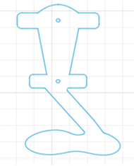
Overall, this study was comprised of four parts. First, a sensitivity analysis was performed to identify the best combination of material and plate thickness to fabricate an AFO. Second, an anterior support AFO virtual model was created as a planar cutout as shown in Figure 1. Third, using the material and thickness pairs selected in point one the planar model was extruded at the proper thickness, virtually folded, and underwent an FEA simulation. Finally, a physical model was created with a cost-effective manufacturing technique to demonstrate the feasibility of the manufacturing technique.
Description of the initial sensitivity analysis
A sensitivity analysis via FEA was performed to find the optimal material based on performance and cost. The simulation considered 11 thermoplastic polymeric materials and was run on a vertical cantilever beam (300mm x 50mm x T), with three different thicknesses "T" (i.e. 3mm, 6mm, and 9mm). The cantilever was fixed on one side, and a 100N force was applied to it, orthogonally to the length and width. The force was applied at the end of the cantilever, 300mm from the constraint. We consider this structural arrangement and loading scheme as a first approximation of the behavior of a user applying a load on an AFO during walking [7], without the necessity to deal with more complex geometry. This information and respective results can be viewed in Table 1. We performed this sensitivity analysis to find an optimal combination of material and plate thickness that would guarantee linear, yet large deformations. A combination of material and plate thickness with maximal deformation on the simplified model between 100 and 250mm indicate a secant angle between the constraint end of the cantilever and its free tip between 18 and 40 degrees, which is compatible with unimpaired dorsiflexion range in walking [8]. Many thermoplastic polymers can deform within such boundries without plasticising. Combination of materials and thickness passing this initial screaning were considered suitable to be tested in an FEA analysis with more complex geometry.
Constructing the 2-dimensional model of the AFO
To create the basis of the 2-dimensional design, there was a reference to TOEOFF® (Allard USA)- an orthosis similar to the desired design. To construct the footplate, geometrical reference points were placed on a sketching plane with appropriate dimensions based on the reference. Then, a spline curve tool was used to achieve the edges of the footplate (Figure 1). The upper structure of the AFO, composed of the ankle and shank support utilized the line, fillet, and dimension tools in Fusion 360. The final 2-dimensional drawing is displayed in Figure 1.
Constructing the 3-dimensional model of the AFO
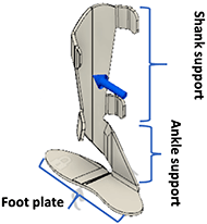
After the planar cutout was complete, it was transformed into a 3-dimensional model.
A 3-dimensional model was made using a sheet metal bending toolbox in Fusion 360's. The 2-dimensional drawing was thickened using Fusion 360's flange tool, as opposed to the more commonly used extrusion tool, and then bent into the shape of the AFO shown in Figure 2. It was bent at 90 degrees at the foot plate and then bent as needed to create a curvature in the shank and ankle support. This process was chosen because it allows to simulate the plastic deformation of the polymeric plate so to simulate the real fabrication process.
FEA Simulation
After the 3-dimensional design had been produced, the FEA simulation in Fusion 360 was carried out. Load configuration was based in part on a technique used in Zou et. al., indicating it is advisable to use a 100N force acting perpendicular and at half the height of the shank support to simulate a person walking with the AFO. [7] The centrod of the distributed force was located about 260mm above the foot plate. The toe region of the footplate was constrained to the ground. Simulations were performed on the entire 3-dimensional design 9 of the materials which pass our initial sensitivity analysis test.
Constructing the physical model
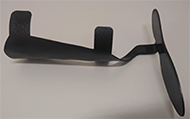
To create the physical model, the drawing of Figure 1 was imported into RDWorks 8.0 software, which sends a file to the laser cutter. A HL-Yeah 1060-130W laser cutter was used to shape the 2-dimensional model in a sheet of thermoplastic resin.
Once the 2-dimensional model was cut, a Wagner heat gun set to 1200 °F was used to warm the polymeric sheet until it was flexible enough to bend with moderate pressure on a 114.3 mm (4.5 inch) diameter metal cylinder. This achieved the curve of the shank support that would surround the user's anterior lower leg, as previously modelled in our 3-Dimensional CAD model.
Finally, the ankle support was bent at a 90 degree angle to the footplate. Once cooling was complete, the product was finished. The model is modified based on weak points determined by FEA and the analysis of other common orthoses. Weak points can be reinforced by layers of crosslinked thermoplastic sheets.
| Material | 3mm | 6mm | 9mm | Material | 3mm | 6mm | 9mm |
|---|---|---|---|---|---|---|---|
| Acetal Resin | 849.7 | 108.2 | 32.4 | Nylon Molybdenum Disulphide | 856.4 | 108.6 | 32.45 |
| Acrylonitrile butadiene styrene (ABS) | 1106 | 140.8 | 42.12 | Polyaryletherketone (PAEK) | 2200 | 281.1 | 84.4 |
| Acrylic | 913.9 | 115.9 | 34.66 | Pentachlorophenol (PBT) Plastic | 265.2 | 33.99 | 10.23 |
| Liquid crystal polymer (LCP) Plastic | 176.1 | 22.33 | 6.673 | Polyethylene High Density | 2704 | 344 | 103.1 |
| Nylon 6 | 909.8 | 115.4 | 34.48 | Polystyrene High Impact | 1304 | 165.7 | 49.62 |
| Nylon 6/6 | 856.4 | 108.6 | 32.45 |
RESULTS
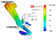
In this study, the optimal material/thickness combination can be defined as the solution of our sensitivity analysis where 1) the maximum deformation remains within the desired range of 100-250 mm, 2) the cost is lowest, and 3) the weight is lowest. Ultimately, 9 mm thickness models were not considered due to weight restrictions. Based on these parameters, the results in Table 1 demonstrate that the 6 mm thick model would work with the majority of the materials we selected., It can be seen that a 3mm plate would produce physically impossible results with deformation larger than the lenght of the cantilever for most materials except Liquid Crystal polymer (LCP) Plastic and Pentachlorophenol (PBT) Plastic.
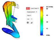
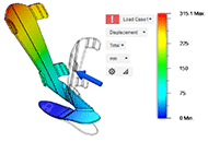
The final set of simulations was performed on a geometrically complex model of the AFO with a 6 mm thickness and a 100 N applied force. Figure 4 shows the results of using ABS plastic, Figure 5 uses LCP plastic, and Figure 6 uses acetal resin. It is interesting to see how the design is able to support the progressive deformation of dorsiflexion (seen mostly in Figure 5) and toe extension (Figure 4 and Figure 6). This simulation was done to see if the design would properly deform given forces approximating to those likely to be created by the AFO's user. The total deformation and rotation of the toe-ankle complex allowed by each material is presented in Table 2, together with the rotational stiffness of the AFO.
| Material | Deflection [mm] | Angle [deg] | Stiffness [Nm/deg] | Material | Deflection [mm] | Angle [deg] | Stiffness [Nm/deg] |
|---|---|---|---|---|---|---|---|
| Acetal Resin | 315.1 | 50.47 | 0.52 | Nylon 6/6 | 312.9 | 50.28 | 0.52 |
| Acrylonitrile butadiene styrene (ABS) | 408.4 | 57.52 | 0.45 | Nylon Molybdenum Disulphide | 312.9 | 50.29 | 0.52 |
| Acrylic | 334.5 | 52.14 | 0.50 | Pentachlorophenol (PBT) Plastic | 100.8 | 21.19 | 1.23 |
| Liquid crystal polymer (LCP) Plastic | 64.34 | 13.90 | 1.87 | Polystyrene High Impact | 481.5 | 61.63 | 0.42 |
| Nylon 6 | 332.9 | 52.01 | 0.50 |
DISCUSSION
Overall, the study was an economical approach to AFO design. The purpose of the FEA simulations was to see if the design performs its desired function of support by deforming within a desirable range when the force of walking is applied.The results show that the stiffness of an AFO can be properly set by the appropriate choice of material and thickness pairs. [9] Our analysis show that the stiffness of the AFO is well within the values of commertically available products that go from about 0.2Nm/deg aimed at users without dropfoot, [8] to 4.6 Nm/deg for stiffer carbon fiber AFO design for highly impaired individuals. [10] Finally, we demonstrated that the proposed manufacturing approach is feasible and could be scaled at the industrial level.
REFERENCES
- Dodd KJ, Taylor NF, Damiano DL. A systematic review of the effectiveness of strength-training programs for people with cerebral palsy. Archives of physical medicine and rehabilitation. 2002;83(8):1157-64.
- Alam M, Choudhury IA, Mamat AB. Mechanism and design analysis of articulated ankle foot orthoses for drop-foot. The Scientific World Journal. 2014;2014.
- Jones MW, Morgan E, Shelton JE, Thorogood C. Cerebral palsy: introduction and diagnosis (part I). Journal of Pediatric Health Care. 2007;21(3):146-52.
- Aboutorabi A, Arazpour M, Bani MA, Saeedi H, Head JS. Efficacy of ankle foot orthoses types on walking in children with cerebral palsy: A systematic review. Annals of physical and rehabilitation medicine. 2017;60(6):393-402.
- Huang Y-C, Harbst K, Kotajarvi B, Hansen D, Koff MF, Kitaoka HB, et al. Effects of ankle-foot orthoses on ankle and foot kinematics in patient with ankle osteoarthritis. Archives of physical medicine and rehabilitation. 2006;87(5):710-6.
- Piovesan D, Alladi P, editors. Analysis of an Energy Saving Ratchet-Based Ankle Exoskeleton. ASME 2016 International Design Engineering Technical Conferences and Computers and Information in Engineering Conference; 2016: American Society of Mechanical Engineers Digital Collection.
- Zou D, He T, Dailey M, Smith KE, Silva MJ, Sinacore DR, et al. Experimental and computational analysis of composite ankle-foot orthosis. Journal of rehabilitation research and development. 2014;51(10):1525.
- Baggett B, Young G. Ankle joint dorsiflexion. Establishment of a normal range. Journal of the American Podiatric Medical Association. 1993;83(5):251-4.
- Bregman DJ. Finding a formula for the optimal AFO. Lowe Extremity Review. 2012.
- Bregman D, Rozumalski A, Koops D, De Groot V, Schwartz M, Harlaar J. A new method for evaluating ankle foot orthosis characteristics: BRUCE. Gait & posture. 2009;30(2):144-9.