Proposal And Trial Production Of A Low-Cost Control System For An Electrolarynx Using Arduino
Katsutoshi Oe1, Ryota Shibusawa2, Mutsuhiro Nakashige3
1Nippon Bunri University (Oita, Japan), 2Daiichi Institute of Technology (Kirishima, Japan) , 3Shonan Institute of Technology (Fujisawa, Japan)
INTRODUCTION
Currently, many patients lose the function of the vocal cords themselves, the larynx including the vocal cords, and the vocal cords as a source of sound due to laryngeal injuries such as laryngectomy for the treatment of laryngeal cancer or bruising. These patients lose their laryngeal tone, which is the basis of the human voice, and therefore also their voice. Since voice is a very important method of communication for humans, losing it would be very inconvenient. For such patients, some speech production substitutes have been devised and put into practical use with the aim of reconstructing their sound source.
Electrolarynx, a type of substitute vocalization method, is easy to learn and widely used. However, they have the problem of low articulation due to their monotonous sound quality and require one hand to use. Various studies have been conducted to solve this problem[1-3], but none have yet been put into practical use. We have been studying the use of muscle potential signals of the sternohyoid muscle, one of the cervical muscles involved in speech and voice pitch control, to control the pitch and on/off of the sound generated by an electrolarynx, thereby improving comprehension by adding intonation and making it hands-free.
We have succeeded in estimating speech start/stop and voice pitch from the myoelectric signals and controlling an electrolarynx accordingly[4,5]. Currently, to make the PC-based control system we have been using less expensive, we are building a control system using Arduino, a general-purpose microcontroller board. In this report, we describe the outline of these results.
ELECTROLARYNX
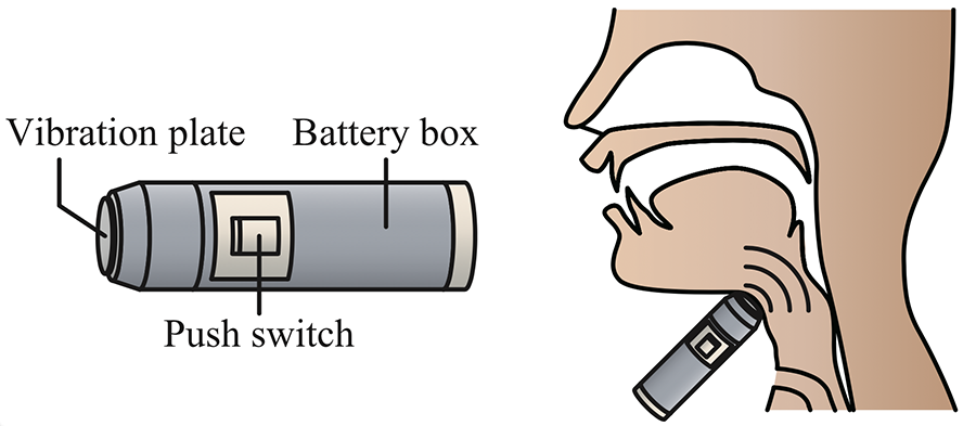
The schematic diagram of an electrolarynx and its usage is shown in Figure 1. A standard electrolarynx has a switch part and a vibration part. When the switch is pushed, the vibration part vibrates. The vibration part is pressed against the neck to transmit vibrations into the body, which are used as a substitute for the vocal cords sounds to produce speech. It is small, lightweight, portable, and can be used as soon as the post-operative wound is stabilized. It has the advantage that even the elderly and patients with reduced physical strength can speak relatively easily. However, the frequency of the electrolarynx vibration is constant, and even those with variable frequencies are difficult to control, resulting in a monotonous sound quality and reduced articulation. Therefore, researches are underway to add inflection to voice by controlling vibration frequencies in various ways[1-3].
CONTROL SYSTEM WITH ARDUINO
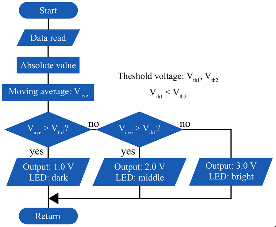
We have successfully controlled the on/off of the electrolarynx and the pitch of voice in three levels (high, middle, and low) using the myoelectric signals of the sternohyoid muscle[4,5]. Figure 2 shows the flowchart of tone control. Since the sternohyoid muscle has the function of stretching the vocal cords during low voice, it controls the electrolarynx to produce low tones when it is active, that is, when the myoelectric signal is strong, and to produce high tones when the myoelectric signal is weak. The electrolarynx used in this study produces a sound whose pitch is proportional to the input voltage.
The threshold values Vth1 and Vth2 (Vth1 < Vth2) are defined in advance, and when the value Vave after signal processing is larger than Vth1, the output control voltage is low (1.0V) for a low tone generation. When Vave is between Vth1 and Vth2, a medium control voltage (2.0V) is output to generate a medium-height sound. If Vave is less than Vth2, a high voltage (3.0V) control signal is output to generate a high tone.
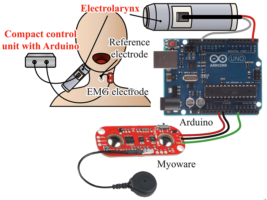
This control system was originally composed of a PC and LabVIEW, but we started to build a control system using Arduino to make it smaller and less expensive with a view to practical use. The schematic diagram of an electrolarynx control system with Arduino is shown in Figure 3. The myoelectric signal is measured by the electrodes of "Myoware" produced by Advancer Technologies, attached to the neck, and it is translated to the control signal for an electrolarynx through signal processing by Arduino.
EVALUATIONS OF PROTOTYPE CONTROL SYSTEM
Objective
To evaluate a prototype electrolarynx control system by myoelectric signals with Arduino and Myoware. Methods
In this evaluation experiment, the control system shown in Figure 3 was used, but the electric larynx was replaced by a green LED to visualize the control results. Therefore, in this evaluation system, the brightness of the green LED (dark, middle, or bright) indicated the sound tone (low, middle, or high). The experimental procedure was as follows.
- The subject wearing the control system was asked to exert force on the sternohyoid muscle with awareness of three different vocalizations at high, middle, and low pitches.
- According to the flowchart in Figure 2, the moving average of the measured sternohyoid muscle myopotential signals was obtained, the values were compared with the preset thresholds Vth1 and Vth2, the pitch frequency control signal was generated according to the results, and the success or failure of the control was evaluated by the appearance of the LED lighting.
Results and Discussions
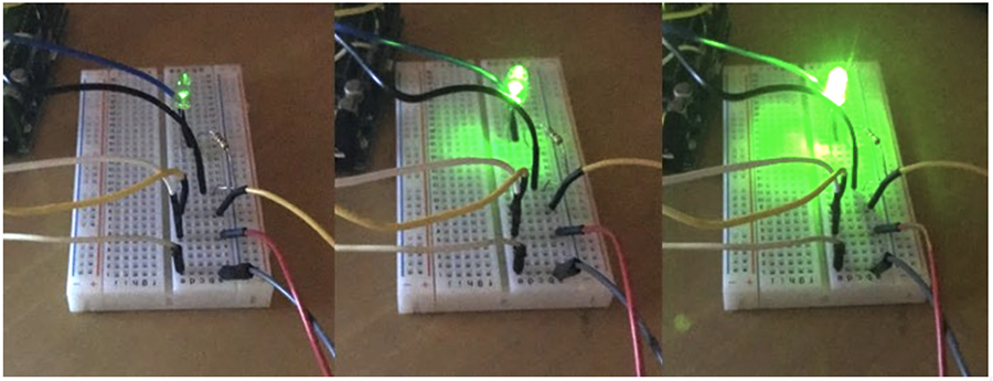
Photo images of LED luminescence when using the prototype control system are shown in Figure 4. When the moving average of the EMG signal was larger than the threshold value Vth1, the LED was dimly lit as shown in a), slightly dimly lit between the threshold values Vth1 and Vth2 as shown in b), and brightly lit when it was less than the threshold value Vth2 as shown in c).
These results indicated that the height control signals generated by the system could be input directly to the electrolarynx to control the height of the generated sound.
CONCLUSIONS
Figure 4. Photo images of the LED when using the prototype control system. Left: a) Low tone, Middle: b) Middle tone, and Right: c) High tone.
To realize an inexpensive system for controlling an electrolarynx with myoelectric signals, we constructed a system using Arduino and Myoware and tested its operation. As a result of devising a method for generating output signals, it was confirmed that it was possible to generate signals to control the pitch of the sound
generated by the electrolarynx using the same operation as that used to control the pitch of the voice in a normal human. In the future, we will plan to add on/off control and drive the electrolarynx to evaluate its performance.
REFERENCES
[1] Richard LG, Artificial laryngeal devices in post-laryngectomy rehabilitation, Laryngoscope, 1975, 85(4):677-689.
[2] Norihiro U, Toru I, Makoto T, Jun-ichi M, Proposal of an electrolarynx having a pitch frequency control function and its evaluation, Trans. Inst. Electrom. Inf. Commun. Eng., 1995 J78-DII(3):571-578.
[3] Ehab AG, James TH, James BK, Garrett BS, Robert EH, Design and implementation of a hands-free electrolarynx device controlled by neck strap muscle electromyographic activity, IEEE Trans. On Biomed. Eng., 2004, 51(2):325-332.
[4] Katsutoshi O, Development of controllable artificial larynx by neck myoelectric signal, Procedia Engineering, 2012, 47:869-872.
[5] Katsutoshi O, An electrolarynx control method using myoelectric signals from the neck, Journal of Robotics and Mechatronics, 2021, 33(4):804-813.
ACKNOWLEDGEMENTS
This work was performed within JSPS KAKENHI Grant Number JP20K11226.