K. Manal1, B. Misialek1, B. Li2, P. Jenks3, B. Gillette3, I. Lockwood3
1KTM LLC, Newark, DE. 2enCore Laboratory, Santa Ana, CA. 3Accudyne Systems Inc, Newark, DE.
INTRODUCTION
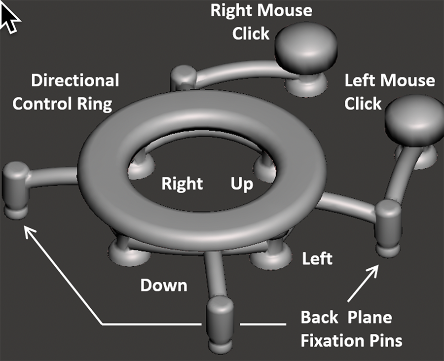
Customer discovery and published work highlights features of an assistive device valued by individuals with severe upper limb paralysis (SULP). [1] These include: the device be intuitive, requiring no complex keystrokes or commands to initiate an action or correct an error; non-fatiguing so it can be used for extended periods of time; portable, so it can be used in as many places as possible; and importantly, easy to set up for caregivers. The Mouth Mouse is an alternate computer input device designed with exactly these features in mind. It is an HID Bluetooth computer mouse with right and left mouse click functionality. Cursor movement is directed by sliding the tongue along a directional control ring, and mouse clicks are initiated by lightly touching the tip of the tongue to the mouse click buttons (Figure 1). The Mouth Mouse can generate straight line, diagonal, and curved cursor trajectories with movement speed proportional to tongue force applied to the control ring. It requires no software be installed on the host computer, and since it is contained entirely within the mouth with no external cabling or hardware, the Mouth Mouse can be used virtually anywhere, and in any position (e.g., sitting up or lying down). In this paper we outline several design features of the Mouth Mouse, describe on-going research activities, and discuss what we envision as future applications of our technology.
DESIGN
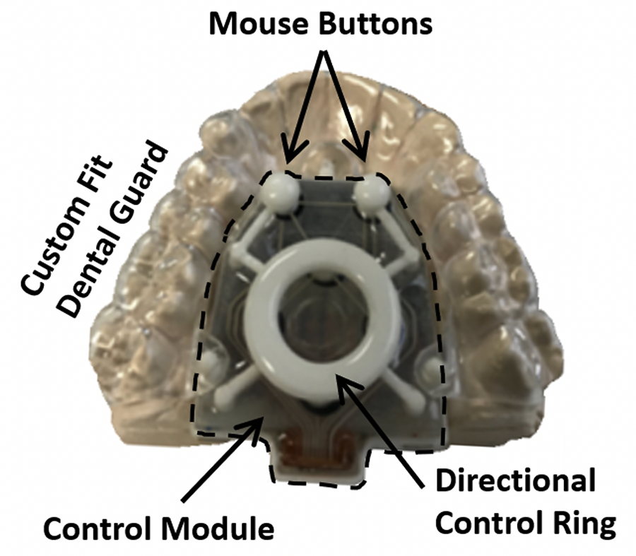
The Mouth Mouse is formed from two distinct components: (i) a control module and (ii) a custom fit dental guard with fixation tabs (Figure 1). The control module and dental guard snap together securely suspending the module in the palatal space between the upper teeth.
Control module
The control module is approximately 41 mm x 33 mm x 15 mm (L, W, H) and weighs 13 grams. The electronics and battery reside within a nylon polymer housing. A selective laser sintering (SLS) process was used to fabricate a uniformly thick housing shell using Class VI FDA approved material for contact with human tissue. The shell was dimensioned slightly larger than the volume of the internal components. The housing is filled with a silicone potting compound protecting the electronics from moisture. This minimalist approach reduced the weight and overall volume of the module improving fit within the palatal space between the upper teeth of most adult users. The back of the nylon housing has 3 stems with hemispherical heads forming the male ends of the three ball and socket snap joints used to connect the control module and the dental guard.
The Mouth Mouse is built around an ESP32-C3 wireless-enabled microcontroller (MCU). This MCU has six available ADC inputs, on-board Bluetooth Low-Energy and WiFi connection capabilities, and various low-power modes to reduce current consumption when not actively in-use. A custom array of six force-sensitive resistors (FSRs) each with a dynamic force range of 1N was designed by Tekscan Inc. specifically for our application.
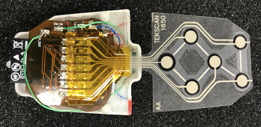
The 6-element sensor is used to detect user tongue input: four sensors for each of the cardinal directions (up, down, left & right) and two for the left and right mouse clicks. The directional sensors are arranged in a diamond pattern, and the mouse button sensors are positioned side-by-side (Figure 2). The ink traces from the six FSRs and a common voltage lead come together in a flexible tail that breaks out to seven 2.5 mm pitch pins soldered to a flexible PCB. The PCB sits on top of the silicone potted electronics and is covered with a rigid backing plate dimensioned to form-fit the perimeter of the housing.
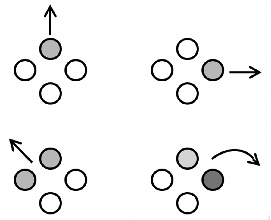
The backing plate is co-bonded to the housing when the embedding silicone is used to seal the battery and circuitry. The backing plate not only seals the electronic components within the housing, but also serves as a rigid base for the 6-element FSR. The length of the tail was chosen so the sensor could be folded back and adhered to the backing plate using a minimal radius of curvature without disrupting the ink traces. The four directional-sensing FSRs are each integrated into a separate non-inverting operational amplifier circuit, along with a fixed feedback resistor and a fixed excitation voltage connected to the non-inverting amplifier input. The feedback resistor for each FSR was selected so that a 1N load would span the full digital output range of the 12 bit ADC. Each FSR exhibits a change in conductance proportional to the pressure applied to the sensor. This arrangement creates a change in gain directly proportional to the pressure applied to a sensor, which in turn produces an output voltage directly proportional to the applied pressure. This directly proportional analog input allows the user to easily move the cursor at different speeds and generate diagonal or curved trajectories when pressure is applied to two or more sensors at once (Figure 3). The mouse button FSRs do not require fine analog control and therefore a much simpler two-resistor voltage divider is used for each and treated as an On/Off switch.
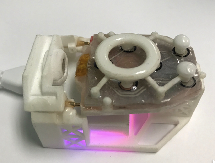
The Mouth Mouse is powered by an embedded rechargeable lithium-ion coin cell battery. Careful management of MCU low-power modes and reduced antenna power levels minimizes the size of the battery required, reducing the size of the overall unit. The battery is charged through two exposed contacts on the outside of the control module housing. The module is placed on a charging cradle with two spring-loaded pins that contact the exposed charging contacts (Figure 4). The positive charging contact is isolated with a diode to prevent short-circuiting or current discharge when the module is inside the mouth. The cradle is equipped with a dedicated charging circuit that increases the charging voltage above the value typically used for a single Li-ion cell to account for the forward voltage drop across the protection diode. Additional battery protection circuitry embedded in the Mouth Mouse provides additional protection against battery overcharging. The Mouth Mouse is powered down by placing it back on the charging stand. A magnet in the charging stand activates an internal reed switch shutting off the module's power supply circuitry without need for an external switch.
The mechanical interface between the tongue and the 6-element FSR is an SLS nylon crab-pad named as such because it resembles the shape of a crab (Figure 5). The crab-pad provides the user orienting features that allow them to quickly adapt their tongue movements to the mouse directional and button controls. The control ring and mouse buttons are supported above the 6-element sensor by flexible arms connected to 4 rigid fixation posts. A ball and socket snap joint at the end of each post connects the crab-pad to the sensor backing plate (Figure 5). Four legs project down from the control ring directly above the 4 directional FSRs. The end of each leg has a load concentrating puck resting approximately 0.25 mm above the force sensing area of the FSR. Similarly, two arms with domed caps, and legs with pucks rest above the mouse button FSRs. Each puck covers 70% of the 3.2 mm diameter sensing area, the recommended configuration by Tekscan Inc. The arms supporting the directional control ring flex proportionally to the position and tongue force applied to the ring closing the gap between the load concentrating pucks and the FSRs. This provides an intuitive method to produce cursor movements using tongue force. The positions and cross-sectional stiffness of the arms were iterated to produce a consistent response to a standard load applied directly above the four sensors. Likewise, tongue force applied to the dome-capped mouse buttons closes the gap between puck and sensor initiating a mouse click.
The Mouth Mouse employs Bluetooth Low Energy for transmission of mouse commands as an HID device and broadcasts a Wi-Fi network as an access point. The Mouth Mouse software is written in C, with modified libraries for Bluetooth communication through the widely implemented HID mouse protocol. The software is capable of over the air (OTA) device configuration and firmware updates, both of which can be accessed through an HTTP and CSS webpage hosted on the device's Wi-Fi network. This precludes the need for exposed communication contacts that might short-circuit in the user's mouth or provide an ingression point for moisture. The device uses the ESP32-C3's deep sleep function to hibernate after a period of inactivity to conserve power, and through the MCU's built in Bluetooth power saving features. The Mouth Mouse sends different types of communication packets at different intervals; advertising packets to initiate a connection are sent every 25 ms, and connection packets which transmit mouse commands are sent every 33.33 ms by default. The mouse commands consist of 2 axis values for cursor movement and 3 commands for the left, right and middle scroll button.
Dental guard
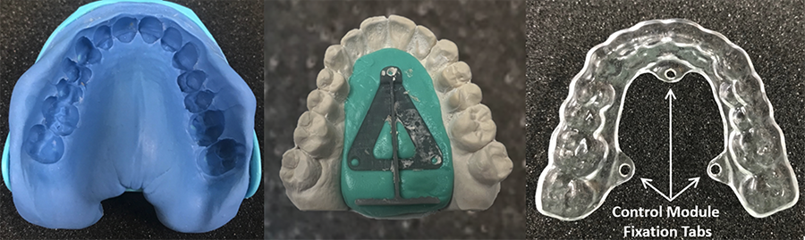
The process of forming a custom fit dental guard starts with obtaining an impression of the upper teeth. A dental tray with impression putty is pressed firmly onto the upper teeth and held in place for approximately 3 minutes for the putty to set. The resulting impression is shown in Figure 6. Dental stone is poured into the impression creating a positive mold of the upper teeth. The palatal space of the stone model is filled with dental putty to the level of the teeth and gumline. The putty is flattened forming a level surface onto which a triangular preform is placed. The apex of the preform is aligned along the midline of the palatal space approximately 5 mm behind the anterior central teeth (Figure 6). A drill bit is pressed through 3 precisely spaced holes near each corner of the triangular preform leaving an impression in the putty. The preform is removed and the stone with putty is placed in a dental vacuum thermoforming machine. A 2 mm polyurethane acrylic sheet is heated and vacuum formed over the stone and putty. A #48 drill bit is used to drill through the acrylic directly above the indentations in the putty forming the female ends of the snap joints. Fixation tab outlines are marked around the holes and the acrylic sheet is cut from the stone model, trimmed, and polished to a smooth finish.
Evaluation
Operational and safety benchmarks were evaluated during development to confirm full operational control of the Mouth Mouse as a Bluetooth computer mouse, and to mitigate potential risks. The risks addressed in this paper focus on the pullout strength of the snap-joints and retention of the dental guard with the added weight of the control module.
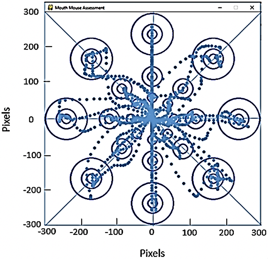
Figure 7 shows cursor trajectories to targets of different diameter and distance from the center of the screen. The image confirms functionality of the directional control ring to generate diagonal and curved paths. The ability to selectively engage the right and left click buttons independently was verified, and the scrolling feature of the device was confirmed. Bluetooth and WiFi connectivity performed as intended, and the device successfully entered low power mode to conserve energy after a pre-defined period of inactivity. The operational benchmarks for the control module met the design criteria.
The crab-pad separating from the backing plate is a potential choking hazard that was identified as a risk and addressed early-on during the design phase. Each snap joint connecting the crab-pad and backing plate was designed to support a pullout force of 13 - 14 N. This was verified with a handheld dynamometer recording pullout force over 100 pullout cycles. The average pullout force was 13.8 N satisfying the benchmark. The combined retaining force (55 N) of the 4 snap joints connecting the crab-pad and backing plate is approximately 4x the maximum adult tongue force (14.1 ± 7.5 N). [2] These data indicate it is unlikely the tongue could dislodge the crab-pad from the backing plate and therefore there is only a minimal risk of such an occurrence. A larger version of the snap joint is used to connect the control module and the dental guard. The mass of the control module is 13 g (< 0.2 N), and therefore a single snap joint is more than sufficient to suspend the weight of the control module. Three snap joints are used to connect the control module and guard, and therefore we are confident there is minimal risk the control module could become uncoupled from the guard when in use. Additionally, retention of the dental guard was assessed to be sufficient to support the combined weight of the control module and the guard (17 g). This was verified experimentally by suspending a 100 g weight from the guard and placing the guard on the dental stone model to confirm retention was sufficient to suspend the weight. This corresponds to a 6x safety factor, and thus there is minimal risk the dental guard and control module will separate from the teeth when using the Mouth Mouse.
DISCUSSION
The Mouth Mouse is an alternate computer input device designed for people with SULP. Bench testing during design and development met operational and safety goals. The effectiveness of the Mouth Mouse as a computer input device is currently being evaluated by a group of able-bodied participants. Preliminary data suggest there is a small degree of learning when first using the Mouth Mouse. Test subjects to date (n=10) rate "Ease of Use" 4 out of 5, and "Overall Operation" a 6.2 out of 7. Subsequent testing by individuals with SULP will compare performance of the Mouth Mouse and the AT they currently use.
A small pilot study (n=3) has been planned that will explore feasibility of the Mouth Mouse as a controller of an assistive robotic arm. This work will be conducted at the Human Engineering Research Laboratories (HERL) at the University of Pittsburgh. HERL will develop a control interface to convert Mouth Mouse signals to robotic control commands for a JACO robotic arm. The JACO arm can be attached to most wheelchairs increasing an individual's ability to perform activities of daily living independently.
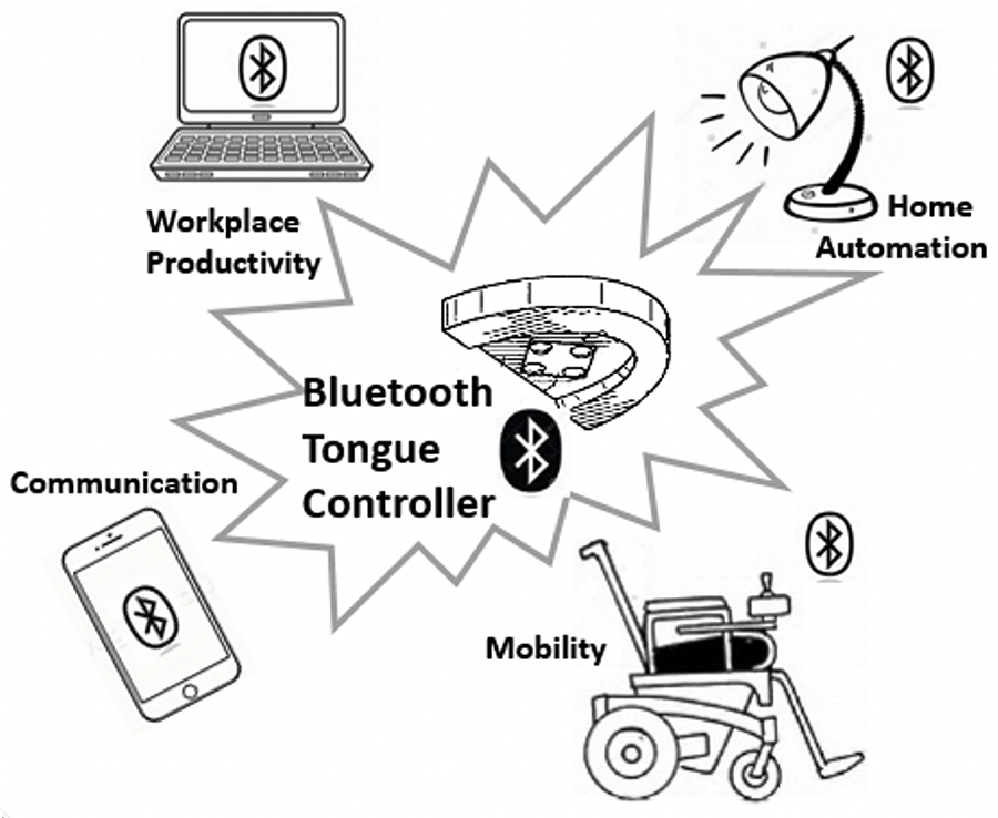
Our long-term vision for the Mouth Mouse is one device to control multiple electronic systems as depicted in Figure 8. We envision the day when a person with complete tetraplegia will use their tongue to self-drive a powered wheelchair, operate an assistive arm, and be able to sit at any computer without requiring specialized hardware and/or software giving them greater independence at home and out in the community.
CONCLUSION
Tongue-control is an underutilized physical option for people with SULP. The Mouth Mouse was designed to meet the wants and needs of this group of users. A risk analysis developed during the design phase, and updated throughout development identified risks, and mitigations to reduce potential hazards. Benchmark testing confirmed that risks were minimized, supporting participant testing of the Mouth Mouse in an intended use population. Testing is currently underway in a group of able-bodied participants and will be followed up with testing by individuals with SULP.
REFERENCES
[1] Gottlieb A, Plotnik M, Kizony R, Katsarou Z, Bostantjopoulou S, Zeilig G. Identification of clinically related requirements of a novel assistive device for people with a high spinal cord injury. PLoS One, 2019 14(6): e0218393.
[2] Sommer JU, Birk R, Hörmann K, Stuck BA. Evaluation of the maximum isometric tongue force of healthy Volunteers. Eur Arch Otorhinolaryngol. 2014 271:3077–3084.
ACKNOWLEDGEMENTS
The contents of this paper were developed under a grant from the National Institute on Disability, Independent Living, and Rehabilitation Research (NIDILRR grant number 90BISB0021). NIDILRR is a Center within the Administration for Community Living (ACL), Department of Health and Human Services (HHS). The contents of this paper do not necessarily represent the policy of NIDILRR, ACL, or HHS, and you should not assume endorsement by the Federal Government.