Grip-it 2 Click-it
Dan Rusnak and Brian Martin
Background
Driving is something that many of us take for granted; however, for a person with a disability, it can be an immense challenge. There are currently many pieces of equipment on the market to allow an individual the ability to drive a vehicle. However, their safety and ability to put on a seat belt is something that is missing in the adaptive driving landscape. According to the National Highway Traffic Safety Administration, of 23,824 individuals that were killed in passenger vehicle accidents in 2020, 51% of these individuals were not wearing seat belts (1). In 2017 it is estimated that 25.5 million individuals had some travel-limiting disability (2). As a team, Dan and Brian created "Grip-it 2 Click-it" to tackle this problem for individuals who can transfer to the original equipment manufacturer (OEM) seat with limited hand functions who need a modification to use the seatbelt independently.
In the fall of 2022, Grip-it 2 Click-it met virtually with Matthew Berwick to talk to him about his seat belting process. Matt has lived with a C5/C6 spinal cord injury for the past 15 years. With his limited hand function, Matt told us that the OEM buckle is not sturdy enough for him to hold the buckle steady. Sometimes, he struggles with his ability to hold on to the buckle, aim the buckle and push down with enough force to "click" the buckle into the receiver. Also, due to limited hand function, finger dexterity, and his lack of triceps strength, releasing the seat belt after being buckled can become difficult and time-consuming.
Problem Statement
Brian has worked professionally in the field of adaptive driving for close to 20 years. Through his professional experience, he noted that there are many pieces of adaptive driving equipment in the world today, but seat belting has been something lacking in the industry. He has observed that individuals who have difficulties buckling a seatbelt either struggle to get buckled-in or choose not to wear a seatbelt. Individuals with limited hand functions need a better way to pull the seatbelt across their body, align the buckle tongue to the buckle receiver, push the seat belt buckle into the receiver, and finally release it independently.
Research Question
Is there a modification that can be made to an OEM seatbelt that allows an individual with limited hand functions the ability to pull the seatbelt across their body, align the buckle tongue to the buckle receiver, push the seat belt buckle into the receiver, and finally release the buckle independently? The "Grip-it 2 Click-it" team believed that we would be able to design a functional seatbelt modification that will allow individuals with limited hand functions the ability to secure the seatbelt easily and safely as well as release the belt independently.
Methods/Approach/Solutions Considered
Virtual Approach to Design
With the course's online nature, the group members are in different cities, as were the individuals we were able to contact to interview. Interviews were conducted via Zoom meetings. Initially, we met with three individuals with spinal cord injuries who drive independently. Two of them drive from their power wheelchair, while one, Matt drives from the OEM seat using a BraunAbility B&D 6-way Transfer Seat. It was determined that while the two who drove from their wheelchair would benefit from modifications, it was beyond the scope of our class to tackle those modifications. Next, we scheduled a follow-up meeting with Matt to discuss his pain points and limitations when using the seatbelt in his vehicle.
After discovering the pain points and limitations, the "Grip-it 2 Click-it" team began generating multiple concepts for seat belting modifications. We then had another meeting with Matt to get his feedback on them. Through conversations, it was determined that the most desired solution was one that would combine two of the concepts: A T-handle would be added to the belt side of the seat belt to enable the ability to grasp the belt, and a pull-up T-handle on a fulcrum would be added to the release button to aide in unbuckling.
During the fall of 2022, a proof of concept was built for this project to ensure that the design would be able to be added to an OEM seatbelt without altering the safety function of the existing equipment or cause us to replace it with non-NTSB evaluated equipment.
Construction of the prototype
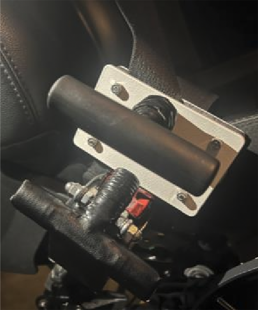
The proposed plan was to build the prototype from everyday materials found at retail hardware stores. This would allow us the flexibility and economy to interchange parts, allowing us room for options, error, and adaptation when testing the device. Since the project team, Dan and Brian, lived in different towns, we went about constructing separate prototypes based on the core ideas we developed in the first semester. We met via Zoom calls to talk about the pros and cons we found in our designs. As we got deeper into prototyping, we realized that the first iteration of our prototype attached to Brian's seatbelt buckle would not work, as our client's buckle differed significantly in shape and flow-through of the belt. Luckily, Dan's Kia Soul had the exact same buckle as Matt's vehicle. This meant that we could no longer be running separate prototyping and would need to meet in person. On March 4th, 2023, we met in Pittsburgh to complete the prototype and proceeded forward with verification testing on the device. The device consisted of two parts: A pulling device made from two plastic electrical covers that "sandwich" the seatbelt buckle, connected with bolts and nuts, which allows normal flow through of the seatbelt. The front side cover had a T-handle mounted to facilitate the seatbelt's pulling and buckling. The second part of the design is another T-handle mounted to a wooden block to act as a fulcrum to release the buckle. Although this is a simple solution, we believe that the design allows the individual with limited hand functions to have increased independence by improving their ability to buckle and unbuckle a seatbelt and improved safety by making it easier to use an OEM seatbelt in a vehicle.
Testing of the prototype
As was expected, we ran through a mixture of different hardware until we were able to find the right size bolts and nuts that held both our buckle device securely and did not interfere with the function of the seatbelt. We experienced a bit of trial and error finding the proper mounting points on our receiver device so that both adaptive solutions fit together properly when they were connected. By using a Beslands Digital Force Gauge (AMF-500) measurement device, we tested the force required to release the seatbelt both with and without our device attached. We found that 12.9 N of downward force was needed to release the buckle without the device, and 10.7 N of upward lift was needed while using the device. By interviewing Matt, we calculated that he used his seatbelt approximately 650 times a year, so we estimated that 700 cycles of buckling and unbuckling would simulate approximately 1 year of use for good measure. We spent an afternoon taking turns buckling and unbuckling the prototypes 700 times to test for durability. At the end of testing, we confirmed that our design was both functional and durable. We marked the nuts to test for movement, and one nut had moved during testing, so we changed hardware to nylon-insert lock nuts to prevent this in the future. Dan then drove around with the device for another 7 days, buckling and unbuckling an additional ~70 times to evaluate the device in a real-world scenario without incident.
User feedback from solution
Prior to meeting with Matt, he liked our design and its proposed function, but wanted it to look a bit more like it "belonged in his vehicle." We found an adhesive leather that matched the interior of his vehicle and went about making the prototype look cleaner and more like it was a natural extension of his seatbelt assembly. Matt tried the devices using a myriad of clothing to be sure that the design was still functional for him in the 4 seasons of Pittsburgh: T-shirt, jacket, sweatshirt, button down shirt, and winter coat. Matt did not note that the style of clothing mattered to the functionality of the device. Matt commented on the look of the device, and while he was pleased overall, the straps connecting it to the receiver stood out, so he asked us to cover those with leather so as not to call attention to the device. Overall, Matt was incredibly pleased with the devices and felt that we had addressed all of his needs.
Solutions Considered from new feedback
We considered Matt's suggestion and cut the leather adhesive tape to the exact shape of the metal straps, creating a much cleaner look.
Description of Final Approach and Design
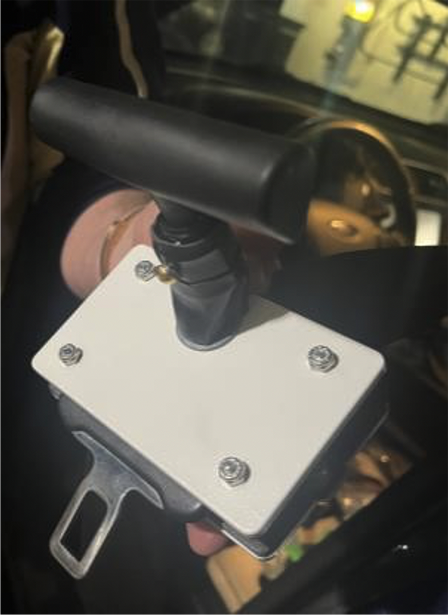
The final prototype of the "Grip-it 2 Click-it" is a two-part design, the buckle side and the receiver side. The buckle side utilizes two rectangular outdoor electrical covers sandwiched horizontally over the belt buckle. The T-handle mount is affixed by drilling a hole in the front plate to attach the offset electrical metallic tube (EMT) which is threaded and held on by a ½" low profile nut. The T-handle, which is a tire patch tool with the metal probe cut off, is then placed inside the EMT and secured with plastic to metal bond epoxy and a 10-24 machine screw. This handle was chosen for its ergonomic shape (Figure 1).
The oblong "football" shape of the buckle is accommodated by a 1" steel two-hole strap attached to the inside of the back plate that adds stability once the plates are torqued over the buckle. High grade outdoor ¾" adhesive weather stripping is attached to the plastic of the buckle for additional grip.
The two electrical plates are placed on either side of the buckle and torqued to be tight enough to hold the buckle secure by four 1 ½" 6-32 machine screws. On the inside of the plates on the upper screws are lock nuts that cause the upper portion of the plates to create a "V" shape that provides downward force on the bottom screws and allows unencumbered flow of the belt. It also adds additional pressure on the bottom buckle end. All four screws are torqued on the front plate with lock nuts to secure the mechanism. Once a proper fit is confirmed, the screws are cut flush with the lock nuts with a rotary tool.
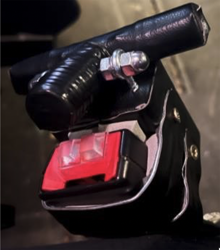
To build the receiver side, we first measured the receiver and cut a block of wood to the same size, approximately 2 ¼ "W x 2 ½ "L x 1 ½ "D. The block is then wrapped with adhesive leather tape. The pull up-T-handle is drilled through at the midpoint and wrapped in leather tape. The fulcrum for the T-handle is created by sinking two 1" long threaded eye bolts with ¼" openings into the block, a 2" piece of ¼"thick all-thread is slid through the hole in the T-handle and the eye bolts. To prevent the T-handle traveling too far to one side of the fulcrum, two lock-nuts are placed on the inside of the eye bolt and two acorn nuts are affixed on the outside of the fulcrum to secure the assembly.
From here, the device is attached to the receiver by bending two 1 ½" steel two-hole straps to fit the receiver tightly. Next, ¾" adhesive weather stripping is added to the inside of the straps and the front of the fulcrum block to create maximum fit and grip. The straps are then pressed by hand as tightly as possible and attached to the fulcrum block with 1 ¼" self-drilling wood screws, making sure to "cradle" the rounded bottom of the receiver with the bottom strap to prevent slippage. Adhesive cabinet anti-slam guards are added to the receiver button to build it up and require less distance for the edge of the fulcrum to travel. After installation of both units, they are easily able to fit together when buckled.
Outcome:
Having the exact buckle assembly as Matt, we were able to thoroughly test our mechanism before installing it on our client's vehicle. We had no problems with installation. Matt was impressed with our design. We first allowed him to attempt to use the device on his own without instruction. After struggling a bit to position the buckle, we then instructed him to reposition his hand from the front of the T-handle to the middle stem. From there he was able to get a better grip and aim the buckle into the receiver with ease. He had no other problems during the testing phase, trying the devices in different clothing to make sure that there would not be issues during the different seasons of the year. He was able to successfully buckle and unbuckle the belt every time. He was particularly impressed with the buckle release mechanism as that significantly improved his functionality. The devices matched his interior very well, and we had him complete the Quebec User Evaluation of Satisfaction with Assistive Technology (QUEST Version 2.0) questionnaire to assess satisfaction ratings of dimensions, weight, ease of adjustment, safety and security, durability, ease of use, comfort, and effectiveness. The scoring is on a scale of 1 to 5, where 1 is "Not satisfied at all" and 5 is "Very satisfied." Matt scored all of the ratings a 5, "very satisfied," for all items except for "effectiveness" which he rated a 4, "quite satisfied." Focusing on the device function questions, Matt gave us a score of 39/40. We excluded the service questions (which were scored as all fives), as they are not applicable to this class. We believe we have built a solid product that has met all of our design goals, and we believe our client agrees.
Cost
The final cost of both complete prototype units is approximately $28 adjusted for quantities of raw materials actually used. The cost total cost of all raw materials was approximately $68. The prototypes were built using readily available common electrical and plumbing components. Most hardware and adhesive material, like leather tape and weather stripping, could not be purchased in specific quantities, so there is extra left over for extra builds or other use. For the items that were able to be purchased individually, such as the electrical box covers, electrical conduit used for the buckle T-handle, eye bolts used for the fulcrum, and PVC plumbing used for the receiver T-handle, there is enough raw material left over to create another full prototype for approximately $10 – 15 more. The block of wood used for the fulcrum base was salvaged from the scrap pile at the local hardware store, so it was not factored in to the price.
Significance
This project aimed to enable individuals with limited hand functions a better way to use a seatbelt. Wearing a seatbelt properly is vital to an individual's safety in a car accident. In 2017 seatbelts were estimated to have saved 14,955 lives in car crashes (1). Individuals with limited hand functions are no different from any other driver; they need to be properly secured in the vehicle to keep them safe while riding in an automobile. Grip-it 2 Click-it will allow individuals with limited hand functions a better way to both put on and release their seatbelt in the future.
References
1. Administration NTaHS. Risky Driving 2023 [Available from: https://www.nhtsa.gov/risky-driving/seat-belts].
2. Lawrence S. Travel Patterns of American Adults with Disabilites, 2023 [Available from: https://www.bts.gov/travel-patterns-with-disabilities].
Acknowledgments
Grip-it 2 Click-it would like to acknowledge the help of our instructors, Dr. David Brienza, Todd Hargroder, Alexandra Delazio, as well as teaching assistant Taychapat Makkong. Special thanks also to Matthew Berwick, our primary client, for his time and feedback throughout the process which made this all possible. Finally, thank the many individuals we have talked to in this process for their insight about the design and their willingness to try the device in the upcoming months.